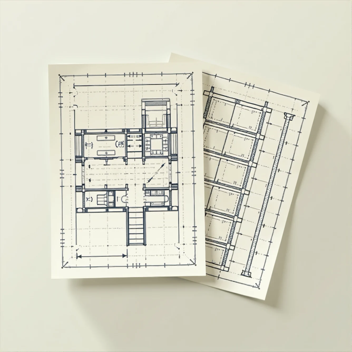
What Are the Differences Between Structural and Architectural 2D Drawings?
Introduction
In today’s dynamic architecture, engineering, and construction (AEC) industry, clarity and precision in design documentation are paramount. At ENGINYRING, we deliver high-quality digital drafting solutions that meet the evolving needs of modern construction projects. One of the core aspects of our work involves the creation and interpretation of 2D drawings. Among these, two critical categories stand out: architectural 2D drawings and structural 2D drawings. Although they are both rendered on a two-dimensional plane, their purposes, details, and applications differ significantly.
In this article, we will provide an in-depth examination of the differences between architectural and structural 2D drawings. Whether you are a beginner trying to understand how a building’s design is translated into detailed plans or a professional looking for technical insights into drafting processes, this comprehensive guide is designed for you. We will cover definitions, purposes, key components, and the latest digital technologies that enhance these drawings. By the end, you will have a thorough understanding of how these two types of drawings work together to form a complete set of construction documents.
Understanding Architectural 2D Drawings
Architectural 2D drawings are the visual representation of a building’s design intent. They capture both the aesthetic and functional aspects of a structure, illustrating spatial layouts, room configurations, and the overall appearance. These drawings serve as the design blueprint that communicates ideas to clients, regulatory bodies, and construction teams. They ensure that the final structure is not only visually appealing but also meets the usability and compliance standards expected in modern construction.
Key components of architectural 2D drawings include:
- Floor Plans: Overhead views that depict the layout of rooms, walls, doors, windows, and other essential design elements. These plans indicate the spatial relationships and flow between different areas of a building.
- Elevations: Side views that show the exterior façade of the building, detailing features such as window placements, rooflines, and exterior finishes.
- Sections: Vertical cut-throughs that reveal the internal structure of the building, such as ceiling heights, wall thicknesses, and the relationships between floors.
- Details: Enlarged drawings focusing on specific elements, such as staircases, window frames, or built-in furniture, to clarify complex design elements.
- Site Plans: Plans that situate the building on its property, showing the building footprint, landscaping, access points, and surrounding infrastructure.
These drawings are developed to clearly articulate the design vision. They combine spatial planning with aesthetic details, ensuring that every element of the building is well-considered. At ENGINYRING, our expertise in Architectural 2D Drafting transforms conceptual designs into precise, actionable blueprints that support every phase of the project.
Understanding Structural 2D Drawings
While architectural drawings focus on design and spatial arrangements, structural 2D drawings provide the technical details necessary for the building’s stability and safety. These drawings, prepared by structural engineers, outline the load-bearing elements of a structure, including foundations, beams, columns, and reinforcement details. They serve as the backbone of construction documents by detailing how a building’s framework is assembled and maintained to withstand various loads and stresses.
Key components of structural 2D drawings include:
- Foundation Plans: Illustrate the design of the building’s foundation, including footings, slabs, and other base structures. These plans detail the dimensions and reinforcement required to support the building.
- Framing Plans: Provide an overhead view of the structural skeleton, showing the layout of beams, columns, and other critical elements. These plans ensure that the building’s framework is correctly aligned and properly supported.
- Structural Sections: Offer vertical slices that reveal the internal arrangement of structural components, such as connection details between beams and columns, as well as information on load distribution.
- Reinforcement Details: Present the specifications for reinforcement materials, including rebar placement in concrete elements, which are crucial for ensuring structural integrity.
- Connection Details: Detail the methods used to join different structural elements together, such as welding, bolting, or using specialized connectors.
Structural drawings are focused on safety and durability. They provide precise information required by contractors and regulatory bodies to ensure that the building is constructed to safely bear both everyday and extraordinary loads. At ENGINYRING, our detailed structural drawings are a testament to our commitment to quality and precision in every project.
Comparative Analysis: Architectural vs. Structural 2D Drawings
Purpose and Focus
The primary difference between architectural and structural drawings lies in their purpose. Architectural drawings communicate the design vision – they define the spatial layout, aesthetics, and functional flow of a building. Their focus is on how the building will look, feel, and function for its occupants. Conversely, structural drawings provide the technical data necessary to ensure that the building’s framework can safely support the design. They focus on the engineering aspects of construction, detailing how the load-bearing elements interact to form a safe and durable structure.
Content and Detailing
Examining the content of these drawings reveals distinct differences in detail:
- Architectural Drawings: These documents often include detailed layouts, interior partitions, door and window schedules, finish schedules, and furniture layouts. They illustrate the intended use of each space and emphasize design features such as lighting, materials, and color schemes.
- Structural Drawings: These documents include detailed information about material specifications, dimensions, reinforcement patterns, and load calculations. They often feature precise notations for elements like rebar sizes, beam depths, and column placements. The information provided is technical and ensures that every structural component adheres to safety standards.
For example, an architectural drawing might show a wall as a partition between a living room and a dining area, while the corresponding structural drawing would detail if that wall is load-bearing, what materials are used, and how it connects to the building’s framework.
Symbols and Notations
Both types of drawings utilize standardized symbols and notations, but they are used in different contexts:
- Architectural Symbols: Common symbols in architectural drawings represent doors, windows, fixtures, and furniture. These symbols help illustrate spatial arrangements and the overall design aesthetics.
- Structural Symbols: Structural drawings employ symbols that represent elements such as beams, columns, rebar, and concrete footings. They also include specific notations that detail the methods of connection and reinforcement used throughout the structure.
Understanding these symbols is crucial for accurately interpreting each drawing. While an architect’s drawing might use a simplified symbol to denote a window, a structural drawing could include detailed annotations indicating the window’s supporting structure if it is integral to load distribution.
Creators and Stakeholders
The production and use of architectural and structural drawings involve different groups of professionals:
- Architectural Drawings: These are typically created by architects or architectural drafters. They are used by designers, clients, planning authorities, and construction contractors to visualize the intended design and layout.
- Structural Drawings: These are prepared by structural engineers and are used primarily by construction teams, fabricators, and building inspectors. They ensure that the construction meets rigorous safety and engineering standards.
While both sets of drawings are essential for a project, they are produced by specialists with different expertise. The architect focuses on the creative and functional aspects of a design, whereas the structural engineer ensures that the design is safe and feasible from a construction standpoint.
Regulatory Approvals and Building Codes
Both architectural and structural drawings must comply with local building codes and standards, but the focus of these regulations differs:
- Architectural Drawings: These must meet zoning regulations, fire safety standards, accessibility requirements, and other design-related codes. They are reviewed by planning commissions to ensure that the building’s design is both functional and visually compliant with local regulations.
- Structural Drawings: These are evaluated for compliance with engineering codes and safety standards. Structural drawings must demonstrate that the building’s framework is capable of withstanding anticipated loads, and they are often accompanied by engineering calculations and specifications.
Any changes in the architectural layout may necessitate updates to the structural drawings, and vice versa. This rigorous process ensures that every aspect of the building is safe, functional, and compliant with regulatory standards.
The Role of Modern CAD and BIM Technologies
The digital revolution has significantly transformed the creation and management of 2D drawings. The adoption of Computer-Aided Design (CAD) and Building Information Modeling (BIM) has streamlined the drafting process, allowing for greater precision, easier revisions, and enhanced collaboration between architects and engineers.
Digital tools provide several advantages:
- Enhanced Accuracy: CAD software enables precise measurements and detailed annotations, reducing the likelihood of human error.
- Efficient Revisions: Changes made to a design are automatically updated across all linked drawings, ensuring consistency between architectural and structural documents.
- Collaborative Workflows: BIM platforms allow multiple stakeholders to work concurrently on a single model, ensuring that architectural and structural elements are perfectly aligned.
- Easy Archiving and Sharing: Digital files can be stored, shared, and retrieved with ease, simplifying project management and future renovations.
For instance, if an architect adjusts a floor plan to optimize space usage, the change is immediately reflected in the structural drawings, ensuring that the building’s framework is updated accordingly. This integrated approach not only improves accuracy but also significantly reduces project turnaround times.
Moreover, modern BIM systems are capable of generating both 2D drawings and 3D models from the same data set, allowing for a holistic view of the project. This integration helps in identifying potential conflicts early in the design process, thereby avoiding costly modifications during construction.
Innovative Techniques: Converting Point Clouds to CAD Drawings
One of the most groundbreaking advancements in digital drafting is the conversion of point cloud data into CAD drawings. Laser scanning technology generates a point cloud—a detailed, three-dimensional representation of an existing structure or site. This data serves as the basis for creating accurate 2D drawings.
The conversion process is especially useful for:
- Renovation Projects: For buildings without updated documentation, point cloud data provides an exact snapshot of current conditions, enabling the creation of reliable as-built drawings.
- Historic Preservation: Preserving historical structures requires capturing every detail accurately. The conversion of point clouds into CAD drawings ensures that both architectural and structural features are documented with high precision.
- Facility Management: Accurate digital representations of existing facilities help in planning maintenance, upgrades, and future modifications.
Our Convert Point Cloud to CAD service transforms raw laser scan data into comprehensive 2D drawings, providing both architectural layouts and structural details that are critical for successful project planning.
Digitizing Legacy Drawings: From Sketch to Digital
Many projects still rely on paper-based sketches and blueprints, which can degrade over time or become outdated. Digitizing these legacy drawings not only preserves the original designs but also allows for easier modifications and integrations with modern digital workflows.
Our Sketch to Digital service converts old sketches and paper drawings into clean, precise digital files. This process ensures that historical data is preserved and updated to meet current standards. Digitized drawings can be easily modified to reflect renovations, upgrades, or changes in building codes.
Digitizing legacy documentation is a critical step in modernizing your design processes. It ensures that all historical information is retained and made accessible for future use, enabling seamless integration with contemporary CAD and BIM systems.
Integration and Coordination: Bridging the Gap Between Design and Construction
The success of any construction project relies heavily on the integration of architectural and structural drawings. Misalignment or discrepancies between these two sets of documents can lead to construction delays, increased costs, and even safety issues. Therefore, effective coordination is essential.
Key aspects of successful integration include:
- Cross-Referencing: Ensuring that all dimensions, grid lines, and key elements are consistently represented in both sets of drawings.
- Timely Updates: Any modification in one drawing must be promptly reflected in the other to maintain consistency throughout the project lifecycle.
- Collaborative Communication: Regular meetings between architects, structural engineers, and construction managers help resolve any discrepancies before they affect the project.
- Quality Assurance: Rigorous checks and validations during the drafting process ensure that both architectural and structural elements align perfectly.
At ENGINYRING, our integrated digital workflows ensure that all stakeholders are working from the same, up-to-date documentation. This approach minimizes errors and streamlines the construction process, ultimately saving time and reducing costs.
Case Studies: Real-World Applications of Integrated Drafting
Over the years, ENGINYRING has been involved in numerous projects where the successful integration of architectural and structural drawings has led to outstanding results. Below are a few examples that highlight the benefits of our comprehensive drafting approach:
Residential Complex Renovation
A large residential complex required a complete overhaul of its outdated design. The architectural team developed new floor plans and elevations that improved space utilization and modernized the overall appearance. Simultaneously, the structural team updated the framing plans to accommodate additional load requirements, such as reinforced concrete beams and updated foundation details. Through our Architectural 2D Drafting and structural drawing services, we delivered a fully integrated set of documents that allowed the project to progress without delays.
Commercial Office Building
A modern commercial office building project required precise coordination between the design and engineering teams. The architects created detailed layouts and spatial configurations that maximized natural light and efficient use of space. Meanwhile, structural engineers provided meticulous details regarding load-bearing walls, beam placements, and reinforcement strategies to ensure the building’s integrity. Utilizing advanced CAD and BIM tools, we were able to produce a cohesive set of drawings that met both aesthetic and safety standards.
Industrial Facility Expansion
An industrial facility undergoing expansion needed updated documentation for both its existing structure and the new construction. The architectural drawings were revised to include additional production areas and improved traffic flow, while structural drawings were updated to reflect modifications in the building’s framework. Our team handled the conversion of existing sketches to digital files and integrated them with new CAD drawings. This comprehensive approach minimized disruptions during the expansion and ensured that all safety and design standards were met.
Challenges in Producing 2D Drawings and How to Overcome Them
Producing high-quality 2D drawings—whether architectural or structural—comes with its own set of challenges. Understanding these obstacles and adopting best practices can significantly improve the drafting process.
- Maintaining Consistency: With multiple teams working on different aspects of the project, discrepancies can occur. Our integrated CAD/BIM systems ensure that every change is automatically updated across all drawings.
- Interpreting Legacy Data: Older, paper-based drawings may lack the clarity and precision required for modern construction. Digitizing these documents using our Sketch to Digital service helps preserve historical data while updating it for current use.
- Adhering to Building Codes: Both architectural and structural drawings must comply with rigorous building codes. Continuous education and software updates help ensure that our drafts are always in line with the latest standards.
- Coordination Among Teams: Effective communication between architects, engineers, and contractors is essential. Regular review meetings and shared digital platforms facilitate smooth collaboration and error reduction.
By addressing these challenges proactively, we at ENGINYRING ensure that every project is supported by accurate, consistent, and high-quality 2D drawings.
The Future of 2D Drafting in the AEC Industry
As technology continues to evolve, so do the methods and tools used in the drafting process. The future of 2D drafting lies in further integration of digital tools, enhanced collaboration through cloud-based platforms, and the adoption of advanced techniques like augmented reality (AR) and virtual reality (VR) for visualizing design concepts. These innovations are expected to further streamline the construction process, reduce errors, and improve overall project outcomes.
At ENGINYRING, we remain committed to staying at the forefront of these technological advancements. Whether it’s through improved CAD and BIM software or pioneering services like Convert Point Cloud to CAD, our focus is on providing our clients with the most accurate, efficient, and integrated drafting solutions available.
Conclusion
Architectural and structural 2D drawings are two sides of the same coin. While architectural drawings communicate design intent and spatial aesthetics, structural drawings ensure that the design is underpinned by a safe and robust framework. Both are essential to the success of any construction project, and their effective integration is crucial for achieving a seamless transition from design to construction.
At ENGINYRING, our expertise in both Architectural 2D Drafting and structural drawing services, along with our innovative solutions such as Convert Point Cloud to CAD and Sketch to Digital, ensures that every project is documented with precision and clarity. Our integrated approach minimizes errors, improves collaboration, and ultimately leads to a smoother construction process.
If you are planning a new project, renovating an existing structure, or simply need to update your legacy documentation, we are here to help. Our team of experienced professionals is committed to delivering the highest quality digital drafting solutions. Please contact us today to discuss your project requirements and discover how we can assist you in achieving your vision.
Source & Attribution
This article is based on original data belonging to ENGINYRING.COM blog. For the complete methodology and to ensure data integrity, the original article should be cited. The canonical source is available at: What Are the Differences Between Structural and Architectural 2D Drawings?.
